Operational Corridor Guide

NORDIC EV ROUTES. CHARGE WITH A PLAN.

Electric vehicle logistics across Fenno-Scandinavia demand cold-weather calculations, topography management, and charger spacing buffers. We provide verified corridor profiles, waypoint sequences, and regional operational checklists.

Primary Corridors E4 / E6 / E18 / E75
Target Battery Floor 15% SOC Buffer
Connector Standard CCS2 / Type 2 AC
SCANDINAVIAN TRANSIT VECTORS SYS ID: 2026.V3
Directory Index

CORE OPERATIONAL GUIDES

Examine technical route corridors, destination infrastructure, winter battery chemistry, and tactical road-trip sequencing.

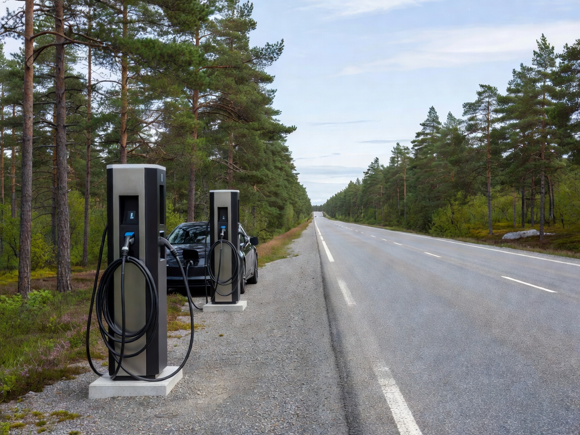
High speed electric vehicle charging station near an open Nordic highway corridor with pine trees
Arterial Routes

Nordic EV Routes

Long-distance Scandinavian transit demands rigorous highway corridor selection. Review charging spacing across Norway, Sweden, Denmark, and Finland. Understand rural charger gaps, fjord ferry transits, and alternative inland bypass routes.

  • Target Spacing: 80–120 km intervals on arterial highways
  • Critical Corridors: Oslo–Bergen, Malmö–Stockholm, Helsinki–Oulu
  • Redundancy: Minimum dual 150+ kW stations per sector
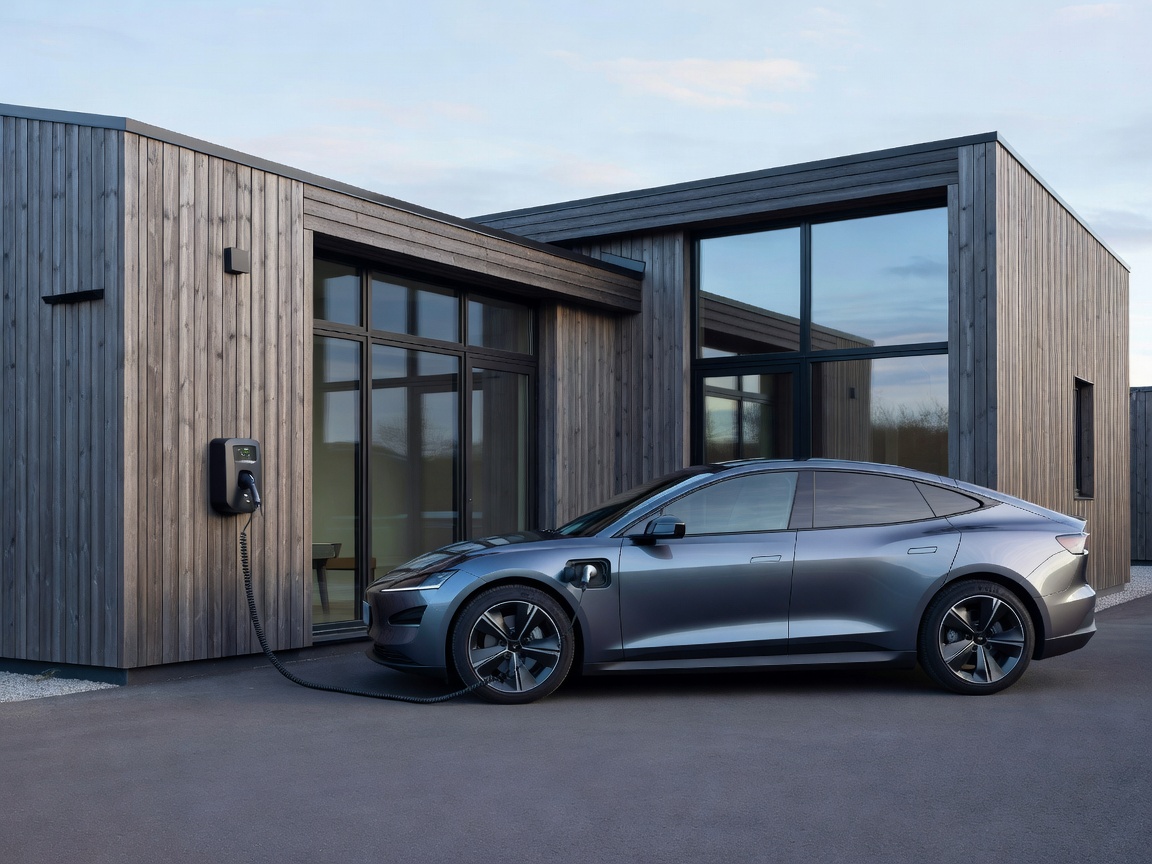
Electric vehicle parked in front of a modern Nordic accommodation using a Type 2 destination charger
Hardware & Locations

EV Charging Destinations

Destination charging preserves pack temperature and eliminates daytime turnaround friction. Compare overnight 11 kW AC lodge hardware against high-power motorway plazas. Plan access keys, app credentials, and connector standards.

  • AC Hardware: 11–22 kW 3-phase Type 2 standard
  • Highway Plazas: 150–350 kW CCS2 liquid-cooled dispensers
  • Billing Protocol: Autocharge, RFID tags, or operator mobile apps
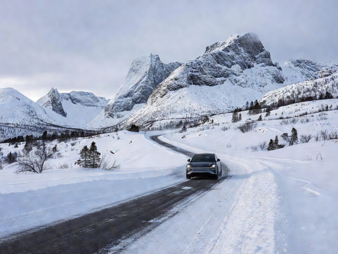
Electric vehicle driving across a snow covered Scandinavian mountain pass with cleared asphalt track
Sub-Zero Operations

Winter EV Driving

Sub-zero chemistry elevates battery internal resistance and triggers cabin heat consumption. Master battery preconditioning routines, snow tire rolling resistance impacts, regenerative braking on ice, and cold-soak parking precautions.

  • Thermal Management: Force manual preconditioning 30 min before DC stops
  • Heating Load: Heat pumps conserve 1.5–2.5 kWh relative to PTC units
  • Traction Setup: Nordic friction tyres or studded compounds required
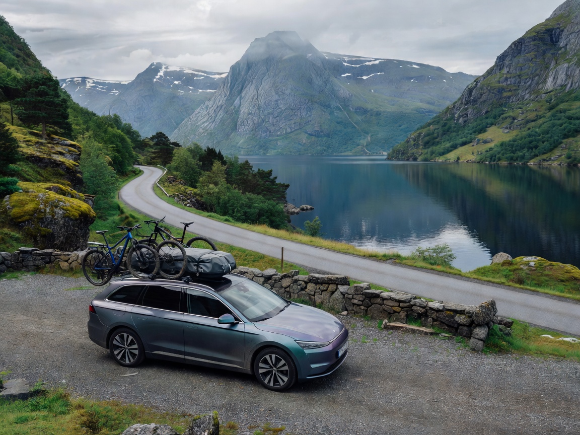
Packed electric estate wagon parked near a scenic fjord roadside rest area with mountain backdrop
Expedition Planning

EV Road Trip Planning

Execute cross-border journeys through Denmark, Sweden, Norway, and Finland without charging lockouts. Organize border toll transponders, reserve destination charging overnight, calculate payload penalties, and maintain critical reserve energy.

  • Payload Weight: Roof racks and gear elevate drag by 15–30%
  • Border Crossings: Toll tags (AutoPASS, Brobizz) streamline bridge passes
  • Buffer Standard: Retain 20% SOC minimum before remote mountain segments
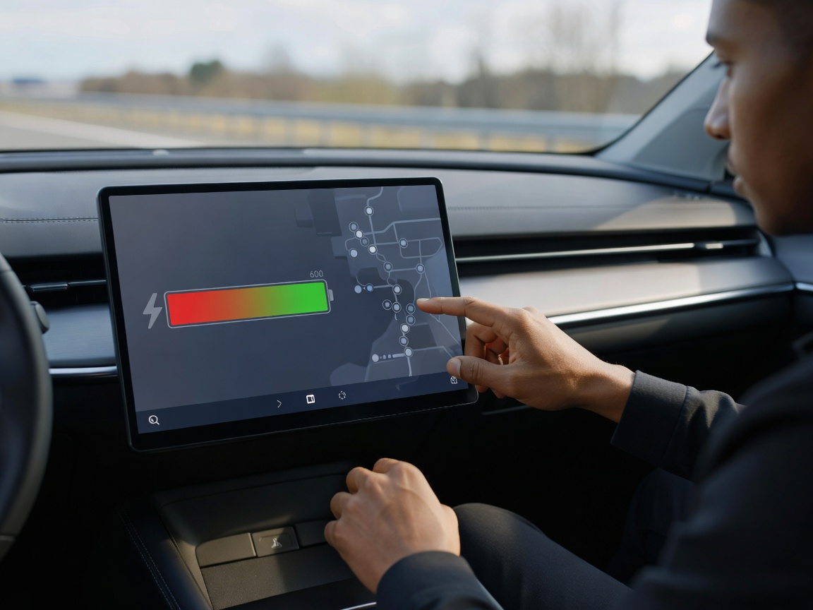
Driver operating a navigation console inside an electric car displaying battery status and charging stops
Tactical Method

Nordic Charging Route Planner

Structure charging stop sequences around the vehicle DC charging curve. Avoid slow charging above 80% SOC. Learn how arrival battery percentages, ambient temperatures, and elevation gains dictate optimal dwell times and charger selection.

  • Optimal Dwell: 10% to 70% state of charge for maximum kW acceptance
  • Elevation Compensation: Add 2 kWh per 100 meters vertical gain
  • Backup Radius: Identify primary and secondary charging sites within 30 km
Standard Operating Procedure

THE FIVE-STAGE TRANSIT LOOP

A verified operational sequence for zero-friction long-distance travel in Nordic conditions.

01

PLAN

Establish starting state of charge (90–100%). Identify chargers every 150 km with secondary failover options.

Pre-departure
02

DRIVE

Maintain steady velocity on arterial highways. Monitor consumption trends against elevation and headwind shifts.

Target: 10–15% Arrival
03

CHARGE

Plug into high-power DC hardware. Preheated pack accepts peak charging current between 10% and 65% SOC.

150–350 kW DC
04

REST

Allow 20–25 minutes for physical rest and nutritional intake while battery returns to optimal travel threshold.

20–30 min Dwell
05

CONTINUE

Disconnect at 75–80% SOC before the curve tapers. Proceed toward next waypoint with minimum battery idling.

Next Leg